Black Floor Drain,Anti Odor Black Floor Drain,Black Tile Insert Floor Drain,Long Rectangular Black Floor Drain Kaiping City Jinqiang Hardware Products Co.,Ltd , https://www.jmpowerdrain.com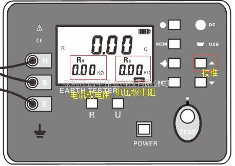
1. Please use the original test line of the instrument. 

Some people do lightning detection for many years, but still do not know or know how to measure the grounding resistance, and think that as long as the instrument measures the results, it is ok, but it is not. DL/T 845.2-2004 General technical conditions for resistance test equipment - Part 2: The requirements of grounding resistance tester for power frequency grounding resistance tester are described in detail. One of them is that the grounding resistance of the current electrode and the voltage electrode (auxiliary ground electrode) must not exceed 500Ω, and the smaller the better. These two parameters are as shown below, and have important discriminating significance for the accuracy of the measured grounding resistance. The low-end instruments on the market do not have this function, and just looking at the ground network test results does not make any sense.
2. Before the test, insert the three wires of the current electrode, voltage electrode, and ground electrode to the corresponding terminals of the instrument (color-to-color correspondence). The three clamps at the other end are clamped together, that is, shorted. Press the test instrument panel. The calibration button on the line resistance calibration.
3. After the line group is calibrated, place the current and voltage poles according to the actual site conditions, and perform the first test on the grounding body. The purpose of the test is to determine whether the grounding resistance of the current pole and the voltage pole is less than 500 ohms. If the instrument shows less than 0.5kΩ, it means that the current pole and the voltage pole grounding resistance are qualified, and the grounding resistance of the ground network to be measured can be tested normally. If the current and voltage resistances show more than 0.5kΩ, you need to adjust the position of the auxiliary electrode or spray water on the auxiliary electrode so that the ground resistance drops below 0kΩ. FW-E08AP Press the test key for a long time to enter the test mode. The FW-E08A has only one test mode. Press it briefly.
4. If OL appears in the current pole, voltage pole, or grounding resistance value during the test, it is necessary to judge whether the test line is conducting. It is recommended to use a multimeter to measure the resistance of the test line, or use a standard resistor to perform self-calibration. The self-calibration method is as follows: The test results should be consistent with the standard resistance values ​​and prove that the wire is OK. Before the test, the wire resistance calibration of step 2 must be performed first.
5. If there is a 0 in the test result, make sure that the clamps on the test leads are reliable.