At present, the CAD/CAM integrated system is limited by the closedness and rigidity of the software model. It is difficult to solve the contradiction between the high efficiency and high function of the CNC machine tool and the inefficiency and low function of the user, and it is not suitable for the highly realistic requirements of the virtual manufacturing system. The main performance is 1 "simulation" and difficult "true" of geometric simulation - the removal of NC machining graphics simulation entity is realized by Boolean subtraction operation. Due to the large amount of computation, the simulation environment can only operate on a single workpiece, and the entire process system cannot be realized. The numerical control machining panorama simulation can not correctly determine the tool rail interference and collision, and can not produce the immersion feeling required by the virtual reality (VR) for the user; 2 the process simulation does not "imitation" is not "true" - CNC machining simulation Ignore (or downplay) the "process", without considering various geometric phenomena and physical phenomena (such as chip generation, etc.) when objects interact in the process system, that is, without substantial simulation of the machining process; "It is difficult to "imitation" - the basic elements of the geometric modeling system are composed of ideal shape geometric shapes, do not contain any physical properties, it is impossible to obtain the actual shape of the workpiece by the cutting mechanism of the workpiece, so the simulation results are distorted. The research work of the influence of error on machining accuracy is still in a qualitative and discrete situation, and the research results are difficult to popularize and apply in actual production. In order to solve the above problems, we choose a large-scale CNC lathe as the research object, and carry out research work around the virtual manufacturing foundation--the numerical control machining process simulation, so that the frontier research of virtual manufacturing is combined with the technical problems of CNC machine tools in China. The simulation of CNC machining process opens up a new way. 1 CNC turning geometry simulation
- Parametric modeling method for numerical control turning features
At present, CNC machining simulation graphics are generally represented by CSG (constructed solid graphics) voxels, B-rep (boundary representation), and feature modeling. Since the geometric boundary elements (points, lines, and faces) of the CSG voxels are implicit in the voxels, it takes a long time to display and draw voxels, and the B-rep notation has a complicated data structure and requires a large amount of data storage space. Therefore, this paper presents a three-dimensional entity with feature modeling. For this reason, based on the turning properties, the geometry of the rotating body is subdivided and abstracted into four basic geometric voxels—cylindrical, conical, spherical (including spherical crowns composed of complex curved surfaces) and threaded surfaces. (A non-porous part can be considered as a special case when the hole in the hole type is zero). In order to realize the geometric simulation of arbitrary shape NC turning machining, a parametric modeling method of feature body is proposed. The core content of the method is as follows: Abstract the machining workpiece into a series of single-piece solid features, and parameterize the driving of the physical feature size to form related graphic features. The workpiece related features are combined in turn according to the processing sequence, and the whole workpiece machining process simulation can be completed. Figure 1a shows the individual features (spherical crown) of Figure 1b. By changing the size L and combining them in sequence, the curved surface shown in Figure 1b can be generated.
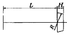
(a) Single characteristics
| 
(b) Monomer constituting entities
|
| Figure 1 Entity parametric modeling |
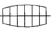
(a) Virtual CNC lathe
| 
(b) Control panel
|
| Figure 2 CNC turning panorama simulation |
(a) Gear shaft machining simulation
| 
(b) Handle processing simulation
|
| Figure 3 Example of CNC turning panorama simulation |
- Numerical Simulation of CNC Turning
The feature-parameter modeling technology significantly improves the speed of CNC turning simulation graphics, making panoramic simulation of the entire CNC lathe (including chucks, turret cutters, guides and beds) possible. In this paper, a virtual CNC lathe is made for the CNC lathe of Shenyang Xinyang Machine Manufacturing Co., Ltd., as shown in Figure 2a. Since the traditional menu bar control is abandoned (various processing information can be input from the virtual panel shown in Fig. 2b and the corresponding response of the virtual lathe actuator is obtained), the virtual processing environment produced has a moderate immersion. Figure 3 shows the simulation of any part turning machining based on the parametric modeling technique in the panoramic environment. Figure 3a shows the gear shaft machining, which mainly simulates turning cylindrical surface, taper surface, end surface, groove, thread and chamfer. Figure 3b shows the handle machining, which mainly simulates turning any curved surface.
2 CNC turning chip simulation
- Chip form
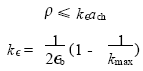
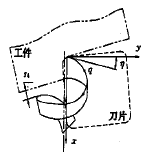
During the cutting process, the chips flow out through the curling of the cutter and form an equal pitch spiral, the shape of which is determined by the outer diameter 2 r of the spiral, the pitch p, and the angle q between the helicoid and the shaft. If the curl rate on the chip is 1/ r x and the transverse curl ratio is 1/ r z , and the outflow direction and the normal angle of the cutting edge (ie, the chip angle) are h , the above three parameters can be expressed as
| (1) |
The hindered and broken conditions after the chips flow out can be divided into the following four basic types:

(a) loose spiral shavings
| 
(b) Hairline
| 
(c) C-shaped chips
|

(d) Spiral chip
| 
(e) Arc chips
| 
(f) gasket scraps
|
| Figure 4 Chip shape feature modeling |
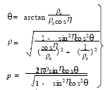
- Continuous spiral chips When the chips flow out along the cutter coils, they do not encounter obstacles and form continuous spirals of different shapes. According to the outer diameter of the spiral and the pitch, they can be divided into loose spirals and spiral chips.
- When the chip fringe angle h is small, the chip rolls up against the workpiece, the chip is bent downward due to the rotation of the workpiece, and the radius of curvature becomes smaller. As the chip continues to flow out, the subsequent chips are wrapped outside, and the diameter thereof is continuously increased. To a certain extent, the chips are broken to form a spring-like chip.
- C-shaped chips or arc chips When the flow angle h is large, the chips are curled and then passed through the workpiece and flow downward to hit the flank, and the chips continue to flow to increase the curl radius, and finally break to form C-shaped chips or arcs. Chip-shaped chips.
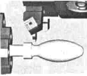
- When the gasket-shaped chip is mainly laterally deformed, the chip flows out to reach the surface to be machined, and the tip of the chip is pushed downward due to the rotation of the workpiece, so that the chip is torsionally deformed, and the chip that continues to flow further moves the front chip further downward, and finally It is twisted to form a washer-shaped chip.
The above chip feature is shown in Figure 4.
- Chip type judgment condition
The chip breaking strain condition is
| (2) |
(a) side view
| 
(b) main view
| 
(c) Top view
|
| Figure 5 Chip formation process |
Where a ch is the chip thickness; e b is the chip breaking strain value; k max is the ratio of the radius of the chip after deformation to its initial crimp radius, generally k max =4.
When cutting with an indexable turning tool, if the formed chips do not satisfy the formula (2), the chips will be prevented from being broken after being discharged, and will easily become tangled debris; if the formula (2) is satisfied, it can be broken and formed. Different types of short chips.
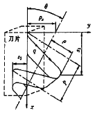
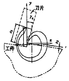
Figure 5 shows the spatial positional relationship between the tool and the workpiece formed by the cutting mechanism. Available from Figure 5
| (3) |
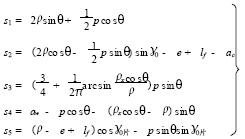
According to the formula (3), the chip type judgment process is shown in Fig. 6. In Fig. 6, s0 is the width direction displacement of the end when the chip is deformed when it hits the cutting surface of the workpiece. When s0 is large, the chips are separated from the workpiece before breaking, and the experimental analysis of s0 (cutting 45 steel and common alloy steel) S0=0.08p+0.7 r sin q
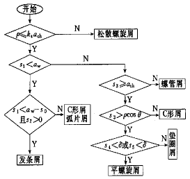
Figure 6 Chip shape judgment block diagram | 
1 Click here to view all news photos
(a) loose spiral shavings | 
1 Click here to view all news photos
(b) Hairline |

(c) C-shaped chips
| 
(d) Spiral chip
|

(e) Arc chips
| 
(f) gasket scraps
|
| Figure 7 Chip simulation example |
Various chip simulation examples shown in Fig. 7 are obtained from Fig. 6 and the characteristic entity parametric modeling method.
3 CNC turning machining quality simulation
- "Three instant heart" forming method
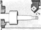
In the ideal cutting process, the process reference of the workpiece coincides with the spindle axis, and there is no spindle axis and process reference drift. At this time, the tool is also in an ideal state, so the workpiece is ideal. During the actual machining process, the spindle will drift due to the motion error, and the “spindle center†will be formed on any cross section where the workpiece is located. The process reference is also affected by various errors of the process system and deviates from the ideal position, forming a “cross-section†on the workpiece. Process transients; The tip point is affected by the clamping error, the guide rail error and the tool wear, which also deviate from the ideal position to form the “knife tipâ€. The above factors work together to make the workpiece form various morphing machining errors, so it can be considered that the profile of the workpiece at any time is the result of the instantaneous movement of the tool tip, the instantaneous center of the process and the instantaneous interaction of the spindle. Let the process instantaneous center be O 1 , the spindle instantaneous center be O 2 , and the tool tip instantaneous center be M. From Fig. 8, the workpiece can be obtained at any time.
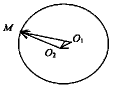
Figure 8 The actual formation process of the cross-section profile of the workpiece |
| O 1 M = O 1 O 2 +O 2 M | (4) |
It is known from equation (4) that the contour radius of the workpiece at any time is the relative displacement of the workpiece process reference and the tool cutting point. - Error aggregation method
In order to derive the actual forming mathematical model of the machined workpiece, a coordinate system should be established for each link of the process dimension chain. It is known from the formula (4) that the actual size of the workpiece at any time is the closed loop of the dimension chain, that is, the displacement of the tip point relative to the workpiece process reference.
To this end, the "error accumulation method" is proposed, that is, the coordinate system is established for each error according to its cause, so that the error is decomposed, and then the tool tip point is chained into the process coordinate system by coordinate transformation to obtain the tool tip point in the process coordinate. Position coordinates under the system. Figure 9 is a specific orientation of each coordinate system under ideal conditions. Figure 10 shows the actual offset of the coordinate system caused by the error during processing. For drawing and calculation, we also concentrate the machining errors to form the vector o tp c. In the figure, S mi is the ideal position coordinate system of the lathe spindle (this system is used as the base system); S g is the lathe guide coordinate system; S ti is the ideal position coordinate system of the turning tool tip; S tp is the tool nose when there is installation deviation Position coordinate system, point c is the actual position of the tool tip due to the error factors such as elastic deformation of the process system, cutting heat and tool wear in this coordinate system; S mp represents the actual position coordinate system of the spindle; S te represents the process coordinates system. The coordinate system shown by the broken line in the figure indicates the rotating coordinate system of each link error.
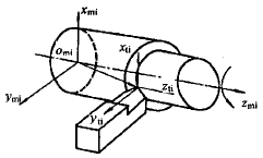
Figure 9 Orientation of each coordinate system under ideal conditions
| 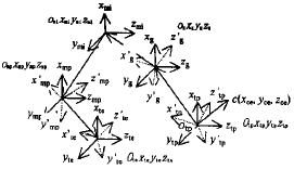
Figure 10 Actual coordinate system offset from the ideal coordinate system
|
It is obvious from Fig. 10 that in order to obtain the actual size of the workpiece (including the error), it is only necessary to transform the vector o tp c (abbreviated as r tp ) in the S tp coordinate system to the S te (abbreviated as r te ) coordinate system. which is
| (5) |
In the formula, a ij (i, j ∈ [1, 4]) is an element in the homogeneous coordinate transformation matrix. 
Figure 11 Turning processing physical simulation graphic display
|
Figure 11 shows the dynamic turning machining graph and calculation results based on equation (5). It shows that the model can simulate the actual forming process of the workpiece, and can predict the diameter, roundness, straightness and surface roughness of the workpiece.
4 Conclusion
- Based on the feature parameterization modeling method, it can simulate the workpiece turning of any shape, and significantly improve the simulation graphics generation speed.
- Chip simulation can effectively solve the chip control problem, which is an important manifestation of the immersion in the manufacturing environment.
- The mathematical model built by the "three instantaneous heart" forming method and the "error accumulation method" can describe the actual machining forming process of the workpiece, determine the functional relationship between multiple error factors and the machining accuracy of the workpiece, predict the processing error trend, and correct the process.
- Virtualization of CNC cutting overall manufacturing environment is immersive to users and is the future simulation trend of cutting.
- The virtual CNC turning machining environment integrating geometric simulation, machining process simulation and machining quality simulation can be fitted with the real processing environment. When the simulation model created by it is confirmed by practice, it can form a real meaning in essence. The actual manufacturing system.
Formula Products For Feed Additive
Amino Acid Liquid,Trace Element Fertilizer,China Acidifier
Other Fertilizer And Chemicals,Pharmaceutical Machinery Co., Ltd. , http://www.nsfertilizers.com