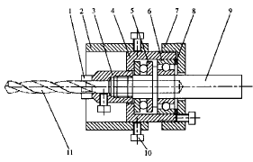
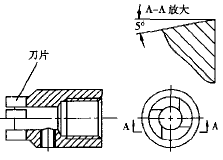
The tooling consists of a limit sleeve 2, a cutter head 3, a bearing housing 4, a thrust bearing 5, a deep groove ball bearing 6, a bearing gland 7, a washer 8, a spindle 9, and a screw 10. The carbide insert is welded to the cutter head. The cutting angle of the cutter head: the rake angle g =0°, the relief angle a = 5°, and the secondary relief angle a 1 =0° (see Figure 3). When machining steel parts, in order to reduce the friction between the tool and the workpiece, the secondary relief angle a 1 = 2 ° ~ 5 °, and chamfered. Fluorinated Fluorobromobenzene & Fluorobenzene 4-Bromo-2-Chloro-1-Fluorobenzene,1-Bromo-3-Chloro-4-Fluorobenzene,3-Chloro-4-Fluorobromobenzene Fluorinated Fluorobenzoic Acid Co., Ltd. , http://www.nsfluorinated.com
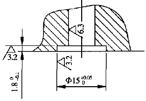
Figure 1 Counterbore structure 
1. Carbide insert 2. Limit sleeve 3. Bit 4. Bearing shell 5. Thrust bearing 8202 6. Deep groove ball bearing 202 7. Bearing gland 8. Washer 9. Spindle 10. Screw 11. Drill
Figure 2 sinking hole flat tool assembly drawing 
Figure 3 cutter head structure diagram
The degree of concentricity between the cutter head and the spindle should be ensured during production. Firstly, the spindle is machined. After the heat treatment, one end of the external thread of the spindle is clamped outward to the three-jaw chuck of the lathe, and the round steel with the end face and the internal thread is screwed onto the external thread of the spindle, and then the cutter head is machined. The shape and inner hole.
This principle should also be followed when grinding the cutter head. First, the cemented carbide insert is welded to the cutter head. When the weld is small, the plaster can be fixed first. The specific method is as follows: first insert the mandrel equal to the thickness of the drill bit into the hole of the cutter head, place the blade in the position to be welded, adjust the flux to the paste and apply it between the blade and the cutter head, and tie the wire with a thin copper wire. After the blade is fastened, the end face of the cutter head and the blade are fixed with gypsum. After the gypsum is solidified, the mandrel is extracted, and then the gypsum is poured into the hole of the cutter head. After the gypsum is solidified, the plaster on the outer circumference of the cutter head is removed, and the weld can be welded. First screw the welded cutter head to the external thread of the tooling spindle; then use the three-jaw chuck to clamp the spindle on the universal tool grinder, smooth the end face of the carbide insert, and grind the outer diameter to the size (ie get The secondary relief angle a 1 =0°); finally, the indexing head is adjusted so that the spindle is tilted up to 5°, and the back of each blade is grounded by the side of the grinding wheel to form a 5° back angle.
When the tool is used, the spindle 9 is clamped to the drill chuck, and the cutter head 3 and the drill bit 11 rotate simultaneously with the spindle. During the machining process, the drill bit 11 first drills the hole, and when the cemented carbide blade approaches the plane, the drill bit is retracted to discharge the iron filings, and then the knife is fed until the limit sleeve contacts the plane of the workpiece, and the drill bit can be withdrawn. Adjust the position of the limit sleeve to control the depth of the counterbore.
The tooling has the advantages of simple structure, high processing precision, high efficiency and convenient use. Our factory uses this tool to machine the counterbore of the valve body on the bench drill. It can control the diameter tolerance of the counterbore within 0.05mm and the depth tolerance is controlled within 0.02mm.
There are often O-ring seals on the joint surface of the hydraulic valve. The diameter and depth dimension accuracy of the counterbore for installing the O-ring seal are relatively high (as shown in Figure 1), and the ordinary boring is difficult to accurately control. It is processed by general-purpose equipment such as lathes and boring machines, and the efficiency is low, and the machining accuracy is not easy to guarantee. In order to solve this problem, the author designed a special tooling, the structure of which is shown in Figure 2.