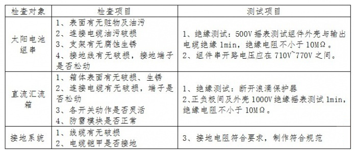
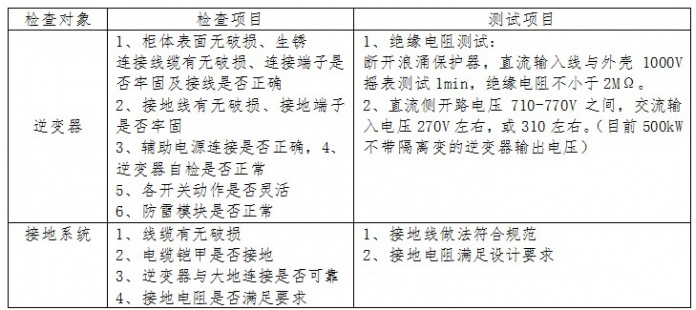
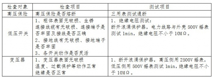
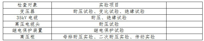
1 Introduction: In today's increasingly grim energy situation, the role and application prospects of photovoltaic power generation as a renewable energy source are increasingly recognized by the society. In order to ensure the reliable grid-connected power generation of photovoltaic power plants, the process and debugging of the photovoltaic power station during commissioning are in progress. It is particularly important to check and test the equipment. This paper uses a 10 MW photovoltaic power system debugging to analyze the debugging process and debugging precautions of the large-scale photovoltaic power plant in the desert and accumulate experience for the commissioning of large-scale photovoltaic power plants. 2 PV power station commissioning analysis 2.1 Introduction to PV Power Stations The 10 MW PV power station consists of 10 1 MW power generating units. The power generating units consist of components, combiner boxes, DC power distribution cabinets, and 500 kW inverters. Each 1 MW is converted into a 1000 kVA after convergence. Double split box change, every 5 boxes change through high voltage series connection into a collector circuit, and 35KV bus line is introduced via a 35KV cable line. The 35kV side uses a single busbar connection. The photovoltaic power station uses two 35kV cables to access the 35kV side bus of the 110kV booster station. Photovoltaic power plants are step-by-step grid-connected after commissioning at each megawatt. 2.2 System Check 2.2.1. Solar Cell String Parallel Detection Before commissioning, please test according to the following table. The open-circuit voltage and insulated power station of each string shall be re-tested when the failure is not satisfied and then tested again until it meets the requirements. 2.2.2. DC Distribution System Testing When the system is detected, if there is a fault, the fault is retested until it meets the requirements. 2.2.3. Inverter System Detection When the system is detected, if there is a fault, the fault is retested until it meets the requirements. 2.2.4. Box Transformer Testing When the system is detected, if there is a fault, the fault is retested until it meets the requirements. 2.2.5. High-voltage cabinet detection When the system is detected, if there is a fault, the fault is retested until it meets the requirements. 2.2.6. Monitoring System Detection The communication monitoring system is connected to the main control room by the RS485 photoelectric converters of the substations through the optical cable. The RS485 side is connected to the substation inverter, the DC cabinet and the box transformer to form the RS485 bus system. The main control room monitors the work data and working status of each substation inverter through computers and monitors. 2.2.7. Cable Inspection 2.3 Photovoltaic Power Plant System Test 2.4 Grid-connected debugging 2.4.1. Power Supply Operation Sequence 2.4.1.1. Closing sequence Above the Array Line Switch → Check all DC input voltage of the DC distribution cabinet → Check whether the 35KV voltage supply is input → Close the box to change the low side switch → Close the inverter Auxiliary power switch → Close the inverter DC input Switch → close the DC switch output switch → close the inverter output AC switch 2.4.1.2. Power-off sequence Breaking Inverter Output AC Switch → Breaking Inverter DC Input Switch → Breaking DC Power Distribution Cabinet Output Switching → Breaking Inverter Auxiliary Power Switch → Breaking Box Transforming Low Side Switch 2.4.1.3. Power-off sequence in emergency Switching station power inverter auxiliary power supply switch → breaking inverter AC output switch → breaking DC power distribution cabinet DC output switch → breaking case change switch or DC power distribution cabinet switch → troubleshooting according to the situation (after box change power failure discharge Can be checked) 2.4.2 Power debugging 2.4.2.1. Power Transmission Process 2.4.2.2.35kV Bus Charging Experiment Apply to the provincial transfer to enter the line XX circuit breaker to charge the 35kV bus. (1) Operate the XX1 switch from the monitoring system to charge the 35kVI bus; (2) Select the bus voltage after charging to check the grounding condition. If there is a single-phase grounding, disconnect the XX1 switch immediately, check the ground fault, and recharge after eliminating the fault. (3) Check that all live parts of the 35kVI bus are operating normally; (4) Check that the polarity of the CT on the high and low voltage side of the main transformer is correct; (5) Check that the 35kV PT cabinet is charged and operating normally, and the secondary side voltage is normal; (6) The nuclear phase of the 35kVI bus and the 110KV line; (7) The nuclear phase of the 35kVI bus and Phase II bus; (8) 35kVI busbar live operation. Close the neutral grounding device after bus charging is completed 2.4.2.3. Line Impact Test Close the collector circuit of the collector circuit and charge the collector circuit. The collector circuit is tested three times for impact: the first power transmission is 3 minutes, and the stop is 2 minutes. After the site is confirmed to be normal, the second impact test is conducted. The second time Power transmission for 5 minutes, stop for 5 minutes, after the site confirmed to be normal after the third impact test, the third power transmission after the observation of the site for 10 minutes without exception after power failure, the line experiment is completed. 2.4.2.4. Transformer Impact Test When the outside line is sent to the switch cabinet inside and outside the factory and everything is normal, power transmission to the inverter rooms is started and a transformer impact test is performed. Transformer impact test to do three times: the first power transmission for 3 minutes, stop for 2 minutes, after the site to confirm all the normal after the second impact test, the second power transmission 5 minutes, stop for 5 minutes, to be confirmed after the scene to confirm the normal Three impact tests, after the third power transmission, observed no abnormalities after 10 minutes at the site, and the experiment of the line was completed, and the transformer was kept running for 24 hours with no load. The transformer is normal: sound is uniform, no noise, no smell, no arc. Precautions: (1) When the on-site personnel monitors the transformer operation status, observe whether the stigm head and the terminal have a flashing discharge phenomenon (the indoor lamp is extinguished when observed). (2) After the transformer impact test is completed, it needs to run for 24 hours with no load. Only when the no-load operation is normal can the inverter be connected to the network for debugging. (3) Within 24 hours before no-load operation of the transformer, the operating status of the transformer shall be observed at the site every 2 hours, and non-stop monitoring of the background shall be conducted. 2.4.2.5 Grid and Commissioning of DC System and Inverter System After the transformer has run for 24 hours at no-load, the DC system and the inverter system are commissioned. The debugging of the DC system and the inverter system is carried out in a unit of 500kW. The power transmission sequence of the DC system and the inverter system is: (1) Closing the outlet breakers of all combiner boxes in the area; (2) Check whether the voltage of each combiner box is normal on the DC cabinet; (3) Check whether the inverter three is relatively insulated; (4) Close the transformer No. 1 circuit breaker under normal output conditions of each of the combiner boxes; (5) Close the inverter auxiliary power switch; (6) Close the DC input switch of the inverter and send a DC power supply to the array to test the inverter. Check whether the DC end of the inverter is normal. (7) Close the two circuit breakers of the DC cabinet to the inverter each time; (8) Close the inverter output AC switch. (9) Detection of inverter after grid connection Automatic switch function detection: Detects the automatic start-up of the inverter in the morning and evening. Check the inverter automatic voltage (MPPT) tracking range. Anti-island protection test; The inverter is connected to the grid for power generation, and the AC switch is disconnected. The analog power grid loses power. Check whether there is an “island†alarm in the current alarm of the inverter and whether the island protection is automatically activated. Output DC component test: When the photovoltaic power station is connected to the grid, the DC component fed to the grid by the grid-connected inverter shall not exceed 0.5% of its AC rated value. Manual switch function detection; Check the inverter manual switch function through the inverter "start/stop" control switch. Remote switch function detection; By monitoring the “start/stop†button of the host computer, check the function of the remote switch of the inverter; after detecting the “start/stop†inverter, can the inverter “stop/start†automatically; check the control flow of the monitoring system. . Inverter efficiency test Measure DC input power and AC output power to calculate efficiency. Temperature protection function test The temperature of the analog inverter cabinet rises and the fan startup function is detected. Detecting the working status of the inverter when the phase sequence is inverted Artificially connects the reverse power phase sequence of the inverter and detects the inverter's grid connection status. Harmonic harmonic test After the photovoltaic power station is connected to the public distribution network, the harmonic voltage of the public connection point shall meet the requirements of GB/T14549-1993 "Power Quality Harmonics of Public Power Grid". Output voltage test The allowable deviation of the three-phase voltage of the AC output of the grid-connected inverter shall not exceed ±3% of the rated voltage. Voltage imbalance test The unbalanced voltage of the public connection points connected to the photovoltaic power plant and the voltage imbalance caused by the photovoltaic power station should meet the requirements of GB/T 15543. The permissible value of the voltage unbalance degree caused by the photovoltaic power station should follow the principle of GB/T 15542. Convert noise When the input voltage of the grid-connected inverter is a rated value, the noise at full load measured by the sound pressure level meter at a distance of 1 m from the horizontal position of the equipment shall not exceed 65 dB. Standby power consumption The standby power consumption of the grid-connected inverter is not greater than the guaranteed value of the contract. (10) In accordance with steps (1) to (6), carry out the grid-connected trial run of the remaining square inverters. 2.4.2.6. Monitoring System Commissioning (1) Check the amount of information monitored; (2) The current and voltage of each channel on the telemetry DC remote cabinet; (3) remote signal inverter on the DC current, voltage, AC voltage, current, real-time power, daily power generation, cumulative power generation, frequency, etc., remote control inverter switch; (4) Signals such as over-temperature alarms, over-temperature trips, high-voltage knife switches, high-voltage fuses, and low-voltage circuit breakers in the remote mailboxes are changed. , Remote measurement transformer low-voltage side three-phase current, three-phase voltage, frequency, power factor, active power, reactive power, active power, reactive power, etc.; (5) Temperature, wind speed, wind direction, and irradiance of the remote environment. (6) The information volume of the photovoltaic field monitoring system can be uploaded to the 110-liter pressure station through the 35kV monitoring system. 2.5 Inspection of the various systems after grid connection 2.5.1. Check the power meter of the gateway and the power meter of the 35KV incoming line cabinet are working properly; 2.5.2. Check the normal data acquisition of the monitoring system; 2.5.3. Check the operating temperatures of box transformers, inverters, combiner boxes, and DC confluence cabinets, as well as the temperatures of key parts such as cable connections and outlet disconnector contacts. 2.5.4. Check that the 35KV switchgear, 110KV transformer and outlet equipment are operating normally. 2.5.5. Under conditions with maximum load power generation, observe whether the device has abnormal alarms or actions. Check the operating temperature of box transformers, inverters, combiner boxes, and DC confluence cabinets, and the temperature of key parts such as cable connections and outlet disconnector contacts. 2.5.6. Check the power quality status of the power station. 2.5.6.1. Voltage deviation: The allowable deviation of three-phase voltage is ±7% of rated voltage, and the allowable deviation of single-phase voltage is +7% and -10% of rated voltage. 2.5.6.2. Voltage unbalance degree: It shall not exceed 2% and shall not exceed 4% for a short time. 2.5.6.3. Frequency deviation: The rated frequency of the grid is 50Hz, and the allowable deviation is ±0.5Hz. 2.5.6.4. Power factor: When the inverter output is greater than 50% of the rated value, the average power factor should not be less than 0.9 (superior or lagged). 2.5.6.5. DC component: The DC component of the inverter feeding the grid should not exceed 1% of its AC rating. 2.5.7. Fully verify the amplitude and phase of each PT and CT of the power station 2.5.8. Completely inspect the working conditions of automatic devices, protective devices, measuring devices, metering devices, meters, control power systems, and fault recorders. 2.5.9. Completely check the upload data of the monitoring system and each subsystem and device. 2.5.10. Check and schedule communication, data transmission, etc. are normal. 2.6 Grid-connected photovoltaic power station commissioning 2.6.1. Completion of the above-mentioned test content After the experience has passed, the photovoltaic power station has a load-carrying operation condition and begins to enter the test run. 2.6.2. Record all running parameters. 2.6.3. Monitor the temperature of critical parts closely during operation. 2.6.4. During the test run, due to the interruption of the operation due to the manufacturing or installation quality of the relevant electromechanical equipment or other reasons, the test run shall be resumed after passing the inspection and the operating time before and after the interruption shall not be cumulatively calculated. 2.6.5. Eliminate and deal with any defects found during commissioning. 2.7 Insufficiency of Inspection and Maintenance of Grid-connected PV Power Plants In the case of doing a good job of safety measures, we will thoroughly examine the problems that have arisen during the operation and meet the requirements for long-term stable operation. 2.8 Transfer and Put into Operation After the grid-connected photovoltaic power plant has passed trial operation for 168 hours and after processing all the defects, it shall transfer it to the production management department. The relevant mechanical and electrical equipment and civil engineering and building transfer shall be promptly carried out according to the contract, and the preliminary acceptance certificate of the photovoltaic power station equipment shall be signed and transferred. Certificates, while calculating the warranty period for the relevant equipment. 3 Conclusion The debugging of the photovoltaic power station process and troubleshooting of the fault directly affects the grid-connected power generation of the power station. Therefore, when the photovoltaic power station is commissioned, it must strictly follow the relevant specifications and design requirements, carefully inspect and test all aspects to ensure that the system is delivered. Before eliminating the problem of concealment, we must be safe and orderly in all aspects of the debugging process. (Li Xiaoyong Ma Jinpeng)
Our BBQ
tools products are divided into 3 pieces BBQ Set, 4 pieces BBQ set, 5 pieces BBQ set, 6 pieces
BBQ set, 10 pieces BBQ set, 24 pieces BBQ set
and so on.The packaging of BBQ Tools have cloth bag, apron bag,cooler bag,aluminum
case, white box,color box,tied on card, suction card, plastic box, bamboo case,
etc..We have all kinds of barbecue tools, barbecue spatula, barbecue fork,
barbecue skewer, barbecue knife, barbecue hairbrush, barbecue silicone
brush, copper wire cleaning brush, barbecue steel wire cleaning brush, corn
fork,salt-pepper tube, steak knife, steak fork, etc. It can not only be
combined into a set but also be in bulk.The BBQ tools we produced, have wooden
handle, stainless steel handle, plastic handle and stainless steel with TPR
handle, a variety of types , whatever you want.
BBQ Set Barbecue Set,Bbq Utensil Set,Barbecue Tool Set,Barbecue Set With Case Yangjiang Yangdong Hongli Industries Co.,Limited , https://www.hongli-industry.com