Phosphate rock powder is a natural, untreated. Phosphate rock powder is a natural, untreated phosphate. When applied to the soil, phosphate rock will become part of the soil. Once applied, the phosphate rock does not leach and it remains in the soil until it is absorbed by the plant. Phosphate contains no harmful acids, it also encourages the growth of bacteria and earthworms in the soil. Phosphate rock powder can be used as a base fertilizer once, and the fertilizer effect can be maintained for several years. At the same time, it is a kind of phosphate fertilizer. This organic fertilizer contains 28% to 32% P2O5. Rock Phosphate Fertilizer,Rock Phosphate Fertilizer Powder,Rock Phosphate Fertilizer 30-35,Rock Phosphate Fertilizer Granules MIDI FEED BIOTECH LIMITED , https://www.midifeed.com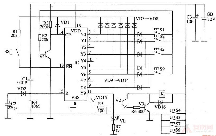
[ Huaqiang Security Network News ]
Do you know the principle of car electronic lock? First understand the concept of electronic lock, electronic lock: it is based on 51 series single-chip microcomputer (AT89051), with the corresponding hardware circuit, complete the password setting, storage, identification and display, drive the electromagnetic actuator and detect its drive Current value, receiving alarm signal from the sensor, sending data, etc.
The MCU receives the entered code and compares it with the password stored in the EEPROM. If the password is correct, the electromagnetic actuator is unlocked; if the password is incorrect, the operator is allowed to re-enter the password, up to three times; if three times If it is not correct, the MCU will alarm the intelligent monitor through the communication line. The single-chip microcomputer sends the unlocking operation and the driving current value of the electromagnetic actuator as the status information to the intelligent monitor at this time, and also sends the alarm information received from the sensor interface to the intelligent monitor as the basis of the intelligent analysis.
Electronic code lock design and electronic lock working principle
The electronic code lock is composed of a decimal counting/pulse distributor integrated circuit CD4017 and a small number of peripheral components. It has the characteristics of high number of cipherable codes and reliable performance, and can be used for the control of door locks, safes or motor vehicle ignition systems.
First, the working principle of the car electronic lock circuit:
The electronic code lock circuit is composed of an input control circuit, a reset circuit, a counter/distributor circuit and a control execution circuit, as shown in the figure.
The input control circuit is composed of password buttons S1, S2, S5, S8, S9 and diodes VD3-VD14, resistor R1 and the like.
The counter/distributor circuit consists of an IC and a transistor V1, resistors R2, R3, and a diode VD1.
The reset circuit is composed of capacitors C1, C2, diodes VD2, VDl5, resistors R4, R5 and buttons S3, S4, S6, S7.
The control performs circuit transistor V2, V3, LED VL, resistor R6, R7, relay (or electronically controlled lock) K and diode VDl6.
After the power is turned on, the +l2V voltage is supplied to the R terminal (15 pin) of the IC to provide a reset high level to reset the IC. The YO terminal (3 pins) outputs a high level, and the remaining outputs are low. level.
When S1 is pressed, the high level of the YO terminal is added to the base of Vl via VD9, Sl and R2, so that Vl is saturated and turned on; after being released, Vl is turned off, and a trigger pulse is generated at the CP end of the IC, and the IC starts. Counting, its Yl end (2 feet) outputs a high level, while the YO end and the remaining output terminals are both low.
Press S2 again, the high level of IC Yl end makes Vl turn on again. After releasing S2, Vl is cut off, IC counts the second pulse, and its Y2 end (4 feet) outputs high level, Yl end and The remaining outputs are all low.
When S8 is pressed, the +l2V voltage forms a closed loop through R3, VDl, Rl and S8 to the ground. When S is released, a trigger pulse is generated at the CP end of the IC, so that the IC counts the third pulse, and its Y3 end (7 feet) Output high level.
When S5 is pressed, the high level of Y3 terminal turns Vl on by VD11, S5 and R2. When S5 is released, Vl is cut off, IC counts the fourth pulse, and Y4 terminal (10 pin) outputs high level.
Press S8 again, the Y5 end of lC (l foot) becomes high again; press S2 to make the Y6 end of the IC go high; press S9 to make the Y7 end of lC go high Level; press S8 to make the Y8 end of the IC go high; press S5 to make the Yg end of the IC output high level, then VL lights up, V2 and V3 turn on, relay (or electricity Control lock) K action, open the lock.
At the same time, the high level of the Y9 terminal is also charged to C2 via VDl5 and R5. When C2 is full (after a few seconds), VD2 is turned on, and the IC is reset by the high-level pulse of the l5 pin, and the output of the YO terminal is high. Electricity, V2 and V3 are cut off, K is released, and VL is extinguished.
The unlock code for this circuit is 128582985. You can change the password by changing the wiring position of each button as needed.
If you do not know the password and accidentally press the buttons S3, S4, S6 and S7, the IC is forced to reset, and the YO terminal outputs a high level and cannot be unlocked.
Component selection
Rl-R7 uses 1/4W carbon film resistor or metal film resistor.
Cl uses monolithic capacitors or polyester capacitors; both C2 and C3 use aluminum electrolytic capacitors with a withstand voltage of 16V.
VDl-VDl5 selects lN4148 type silicon switch diode for use; VDl6 selects 1N4007 type silicon rectifier diode for use.
Vl and V2 select S9013 or 3DG9013 silicon NPN transistor; V3 selects C8050 or S8050 silicon NPN transistor.
The IC uses a CD4017 or CC4017 type decimal count/divider integrated circuit.
S1-S9 selects the moving (normally open) type micro button.
K selects l2V relay or electric lock.