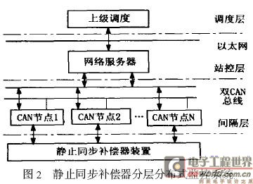
1 Introduction The full name of the CAN bus is ControllerAreaNetworkBus, referred to as the controller local network bus, which is a kind of field bus, which is a serial communication network that effectively supports distributed control or real-time control. CAN is the abbreviation of Controller Area Network (CAN). It was developed by German BOSCH company, which is famous for developing and producing automotive electronics products, and eventually became an international standard (ISO118?8). It is one of the most widely used fieldbuses in the world. In North America and Western Europe, the CAN bus protocol has become the standard bus for automotive computer control systems and embedded industrial control LANs, and has the J1939 protocol designed for large trucks and heavy machinery vehicles with CAN as the underlying protocol. In recent years, its high reliability and good error detection capability have been valued and widely used in automotive computer control systems and industrial environments with harsh ambient temperatures, strong electromagnetic radiation and high vibration. The CAN controller works in a multi-master mode, and each node in the network can compete to send data to the bus according to the bus access priority (depending on the message identifier) ​​using a lossless structure of bit-by-bit arbitration, and the CAN protocol abolishes the station. Address coding, and instead of encoding the communication data, allows different nodes to receive the same data at the same time. These characteristics make the data communication between the nodes of the network formed by the CAN bus real-time and easy to form redundancy. Structure to improve system reliability and system flexibility. The use of RS-485 can only constitute a master-slave structure system, and the communication method can only be carried out in the manner of polling by the primary station, and the real-time performance and reliability of the system are poor. This paper designs a dual CAN bus hierarchical distributed monitoring system based on the DS80C390 chip with two independent CAN modules in Dallas, USA, and applies it to the power system synchronous static compensator (STATCOM). 2 intelligent dual CAN bus node Dallas' high-end single-chip DS80C390 is an embedded high-speed microprocessor chip with dual CAN modules: each machine cycle only contains 4 clock cycles, four times faster than the 8051 microcontroller; supports a maximum crystal frequency of 40MHz, single instruction cycle 100ns Compatible with 80C52 and compatible with 8051 instructions; there are 4 8-bit IO ports, 3 16-bit timers, 256-byte RAM, 4kB internal static SRAM, 16 interrupt sources, 6 of which are external interrupt sources; Line port, dual CAN port and dual data pointer. The structure of the intelligent CAN node using the DS80C390 microcontroller as the core is shown in Figure 1. It consists of DS80C390 MCU, 8255, A/D conversion and PCA82C250CAN transceiver. The external program memory uses Atmel's AT49F010 chip, the fastest read time is 45ns, the erase cycle time is 10s; the data memory uses HY628100SOP, the chip is a high-speed CMOS static RAM; A/D converter ADS7864 is Texas Instruments (TI) Burr-Brown Products' new dual 4-channel A/D converter with fast 6-channel fully differential input enables simultaneous six-channel signal sampling at 500kHz sampling rate. The clock chip selects the DS12887, which can be used to directly replace the clock calendar chip on the IBMPC. The CAN transceiver interface circuit uses the PCA82C250 produced by PHILIP to achieve level conversion to meet CAN communication requirements. The intelligent dual CAN node function mainly includes the following: reading the value of the dial switch, and using the data as part of the ID to set the ID; starting the A?D conversion, each conversion channel collects 1000 points in the AC weekly wave. That is, every 20Ls is converted, the data is stored in the external data transmission buffer. When the host computer summons the data, it is sent by CAN; the calendar clock is started, when the fault occurs, the fault time is recorded, and an external interrupt request INT0 or INT1 is generated. . 3 layered distributed monitoring system DS80C390 integrates two CAN interface modules on-chip, which has high reliability and is suitable for implementing dual CAN line hierarchical distributed monitoring system. The circuit block diagram of the hierarchical distributed monitoring system of the power system static synchronous compensator is shown in Figure 2. The whole monitoring system is divided into a scheduling layer, a station control layer and a bay level. 3.1 Scheduling layer The scheduling layer includes a superordinate scheduling computer and a telecontrol workstation computer, etc., and can communicate with the central monitoring computer network server of the station control layer through a modem dial-up or through an Ethernet. The monitoring screen of the scheduling layer is issued by the web server of the station control layer. The scheduling layer is the management layer of the monitoring system. 3.2 station control layer The station control layer includes a central monitoring network server (WebServ2er). The WEB server is the core of the entire monitoring system, and completes all monitoring functions of the system and is distributed to the scheduling layer through the network. The WEB server of the station control layer includes the PC2CAN card and the network card, etc., communicates with the locally monitored CAN node through the PC2CAN card bus, completes the blocking pulse and trip operation of the device, blocks the fault indication, the water cooling alarm and the fault indication, and the voice alarm; The output voltage and system voltage of the static synchronous compensator are collected; the station control layer is connected to the network through the network card and the scheduling layer. 3.3 spacer layer A total of 40 bottom-level monitoring dual CAN nodes (dual CAN units) are set in the bay. Each bottom-level monitoring CAN node sets the unit number with a jumper and displays the set unit number with a digital tube. The dual CAN node continuously performs three channels of analog recording. When receiving the blocking or tripping signal, it continues to record 2 cycles of recording data before and after recording for 2 cycles, and sends it to the centralized monitoring computer WEB server of the station control layer. 4 software design The MCU monitoring program was developed with KeilC51 and debugged on KeiluVision7.0. The software design of the CAN node adopts a modular design method. In the initialization of the DS80C390, the internal registers are initialized to determine the memory allocation. Its settings are as follows: SA EQU1 IDMDQU2 CMAEQU1 P4CNT5-3EQU 100B P4CNT2-0 EQU100B P5CNT3-0EQU100B The program adopts the interrupt mode. After each program is initialized, it dispatches to the corresponding interrupt service subroutine according to different interrupts. In the interrupt service program, the MCU will send the recorded information through the CAN, which realizes the fault recording function. The system software can be upgraded online using the serial port. 5 Conclusion In this paper, the DS80C390 dual CAN bus hierarchical distributed monitoring system is developed and applied in the power system static synchronous compensator, which satisfies the requirements of wide distribution and high real-time requirements of various control objects in the power system, which greatly improves the system security. Sex, reliability and immunity. There are two main Bonded NdFeB Magnet manufacturing methods: Bonded Injection Moulding NdFeB Bonded Injection Moulding Ndfeb,Neodymium Bonded Electrical Magnet Ring,Ndfeb Plastic Injected Bonded Magnet Jinyu Magnet (Ningbo) Co., Ltd. , http://www.magnetbonwin.com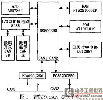
:
ï‚·Bonded Injection Plastic Moulding NdFeB
ï‚·Bonded Compression Moulding Ndfeb
Injection Plastic Ndfeb Magnet , a kind of new-generation composite material made from permanent magnetic powder and plastic, has outstanding magnetic properties and plastic properties and features high size precision and exceptional shock resistance. It can be processed into various components with complicated shapes, thus can be used in the industries of micro or special motors, office equipment, intrument, meter, and beeper. Custom design will be available.
Production Chart of Bonded Injection Plastic Moulding NdFeB
Bonded Ndfeb Magnet has advantages and that's why customers choose:
1. Design and manufacturing of orientation moulds were carried out.
2. Having high dimensional precision and impact-resistance. Capable of forming products with inlay.
3. The Injection Plastic Moulding parts are suitable for forming products with various shaps and thin walls.
4. Muti-polar magnetization can be carried out according customers' requirements.
Application of Bonded Injection Moulding Ndfeb magnets:
•Different kinds of micro-special motor
•House electric apparatus
•Synchronization electric motor
•DC motors
•Instruments for Auto
•Time gauge
1 time
Window._bd_share_config = { "common": { "bdSnsKey": {}, "bdText": "", "bdMini": "2", "bdMiniList": false, "bdPic": "", "bdStyle": " 0", "bdSize": "24" }, "share": {}, "image": { "viewList": ["qzone", "tsina", "tqq", "renren", "weixin"], "viewText": "Share to:", "viewSize": "16" }, "selectShare": { "bdContainerClass": null, "bdSelectMiniList": ["qzone", "tsina", "tqq", "renren" , "weixin"] } }; with (document) 0[(getElementsByTagName('head')[0] || body).appendChild(createElement('script')).src = 'http://bdimg.share. Baidu.com/static/api/js/share.js?v=89860593.js?cdnversion=' + ~(-new Date() / 36e5)];