Parametric Surfaces of discrete <br> <br> for discrete parametric surfaces, the present study more. In this paper, the quadrilateral tree is used to adaptively discretize the surface, that is, the discrete precision allowed by the discrete time is calculated according to the machining precision required by the surface, and then the surface is recursively subdivided according to the discrete precision. When the recursive subdivision process is judged to be partially flat within the discrete precision allowable precision, it is further subdivided, so that all sub-surface patches are partially flat. Then, each sub-curved piece is converted into four triangular pieces by taking the center of the four corner points of the partially flat sub-surface piece. Thus, after discretization, the parametric surface will have a series of triangular planar slices instead. Through the above processing, the result of the intersection of the plane and the surface will be a continuous polyline. On this basis, the real-time interpolation method of this paper is proposed below. As described above, in the time scalar interpolation, the feed amount in the speed synthesis direction in the interpolation cycle is first calculated according to the feed speed and the interpolation cycle, and at the same time, in the specific interpolation surface process, It must be judged whether interpolation with this feed amount will cause the machining accuracy to exceed the allowable machining error, which is cumbersome to process and significantly reduces the interpolation efficiency. For this reason, this paper avoids this judgment process, and directly processes each segment of the broken line segment obtained above to solve the feed amount in the interpolation cycle. The specific process is: for one of the broken line segments, the length is compared with the feed rate calculated according to the feed rate and the interpolation cycle & is referred to herein as the standard feed amount', and the following judgment is made: Previous page
Cross-sectional plane and the curved surface for generating an initial interpolation point <br> <br> Currently, the form tool path and other parameters generated line method, and ring method section plane cutting method. Among them, the quality of the cutting plane method is higher, so this paper adopts the section plane method. The truncated plane method is a method of generating a tool path by using a set of parallel planes that are generally perpendicular to the XY plane to cut the processed surfaces and use their intersection lines to perform related processing.
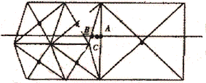
Since the machining surface has a series of simple triangular plane slices through the discretization processing of the previous step, the intersection of the plane and the surface is relatively simple, and only the intersection of the plane and the associated triangular plane piece is required. However, it must be stated here that the discretization of the previous step may cause cracks and folding due to different subdivision levels of adjacent sub-surface patches, see the attached drawings. Of course, this phenomenon can be eliminated by certain means, but this will greatly reduce the discrete efficiency and is not used in this paper. This article will only need to deal with this issue here. When the plane intersects the triangular plane piece at the crack, an intersection line is formed with the crack, such as the line segment AB in the drawing, but in fact, the two points of AB should be the same point of the curved surface, only due to the imperfection of the discrete method. produce. In order to eliminate this phenomenon, the method adopted in this paper is that in this case, the midpoint of the two points A and B is C, which is the intersection of the boundary between the plane and the sub-surface of the crack. 
Cracks appearing during the discretization of the drawing
If the length of the polyline is less than or equal to the standard feed amount, the length of the polyline is used as the feed amount in the interpolation period;
Otherwise, the line length /N is taken as the feed amount for the interpolation period, where: N = INT (line length / standard feed amount) +1.
In this way, the initial interpolation point can be easily obtained, and the initial interpolation point thus obtained will surely satisfy the processing accuracy requirement. Since the method avoids the inspection of the machining accuracy and greatly improves the interpolation efficiency, it is very important for real-time interpolation.